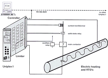
- Expansion up to 150 heating circuits
- Local control panels with Uniplex cards and central operation, indication and logging at the PC
- Temperature limiter independent from the controller acc. to EN 50019 + A4 and VDE 0631
- Suppression of the controller's output signal in case of limiter trip
- Constant temperature controlling (analogue output) or on-off control (relay output)
- Current adjustment acc. to full wave switching principle
- Current regulator in connection with external electronic Solid State Relay
- Supervision of temperature sensors: alarming in case of short circuit or brake
- Indication of max.- and min.-temperature
- Low temperature alarm, blocked during start-up
- Supervision of load-current on minimum and maximum (adjustable)
- Supervision of heating circuit during non-operation
- Storage of the alarm status in case of voltage loss
- Processing of add external limiter alarm
- Limiter relay with 2 normally open contact
- Alarming for each heating circuit
|
- Separate Tmin/Tmax-relay
- Operating condition "Standby" selectable externally
- Input of all parameters by means of control keys
- Input of parameter locked by password
- Indication of all measured values, parameters and alarms by double-line display, value and parameters names and fault indicators in clear text
- Standard distance between control panel and operating terminal up to 800 m
|
- Indication of operating conditions
and general alarms by LED
- Analogue output (4-20 mA) for actual temperature of controller
- One heating circuit needs:
- 2 Pt 100-sensors
- 1 Uniplex I
- power start with electron. Solid State Realy current transformer, contactor
- In case of PC failure, controller
and limiter are operating independently
|

